Overview
Installation
Users Guide
Support
Overview
haneWIN TFTP Server for Windows is a fully-realized TFTP server for all Windows Versions. The TFTP Server runs as a background service and doesn't require permanent attendance. It has been designed to work reliable and secure in background operation mode using a high-performance multithreaded architecture.
The software is implemented in 32- and 64-bit versions.
The software provides a TFTP Server (as application and as NT service)
and TFTP client based on RFCs 1350, 2347-2349 and TFTP mulicast based on RFC 2090.
All TFTP options are supported.
Access control is provided per directory for client IP address and type of
operation.
A native TFTP service is implemented for Windows 200x/XP/Vista/7/8/10.
A Control Panel applet gives interactive access to the service.
Installation
- Requirements
-
Windows 200x/XP/Vista/7/8/10 system configured for TCP/IP
- Installation of the TFTP service on Windows 200x/XP/Vista/7
-
- Install the software by running the setup.
- Use Install TFTP service from the start menu to install the server as service.
- With the control panel applet TFTP Server you can configure and monitor the service.
- Preparation of TFTP Server Application
- Extract the zip-archive, start the application.
Users Guide
The Info Box at startup is displayed only for the unregistered version.
The main windows of the TFTP server displays the status of all active client connections (addresses, progress and type of operation, accessed file).
Running the TFTP server as a Service on Windows 200x/XP/Vista/7
The server can be installed as a service on Windows 200x/XP/Vista/7 for background operation. The service can be configured and monitored by the Control Panel Applet TFTP Server.
- The Service is installed with the command:
TFTP4NT -install
and automatically started on Windows startup. The service can be started and stopped manually through the service control panel. - Use the command
TFTP4NT -remove
to stop and remove the TFTP server service.
- Menus
- File
- Start
- if selected the server accepts new connections.
- Stop
- if selected new connection requests to the server are inhibited. Active connections are not affected.
- View log
- displays a log of all TFTP client requests.
- Exit
- terminates the program
- Options
- Preferences
-
for changing configuration settings.
General
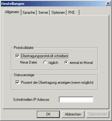
By default the Server is started on all local interfaces. You can restrict the server to one interface only by specifying the local interface IP address.Server
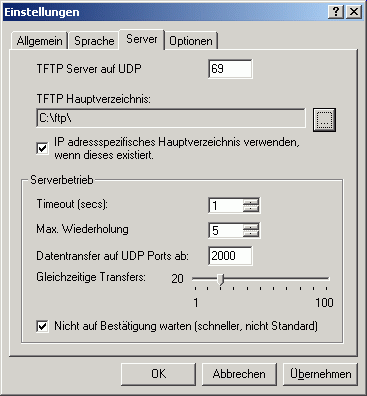
A server root directory must be defined. Any client access outside of the root directory tree is denied. An option enables the server to use a subdirectory of the root directory as a client specific root directory. If this option is enabled and a subdirectory with the IP address of the client exsists, it will be used as the root directory for the client.
The sever allows indicating the range of UDP ports, used for transmitting the data. This allows network administrators to regulate firewall rules, approving the traffic, generated by the server. The UDP port range is defined by specifying the first UDP data port and the number of active clients.Options
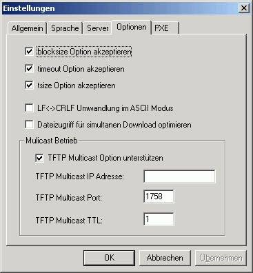
As part of a request TFTP clients can send options to the server. The server can accept or reject the options.- The blocksize option allows the client to choose a data packet size greater than 512 bytes.
- The timeout option allows the client to choose the timeout value for retransmissions. Otherwise the timeout value set on the server will be used.
- With the tsize option the client can inform the server about the total size of the transfered data.
With TFTP Multicast clients can download a file simultanously. The file is sent by the server to the specified multicast address and port. If more than one multicast transfer is started the multicast port number is incremented.PXE
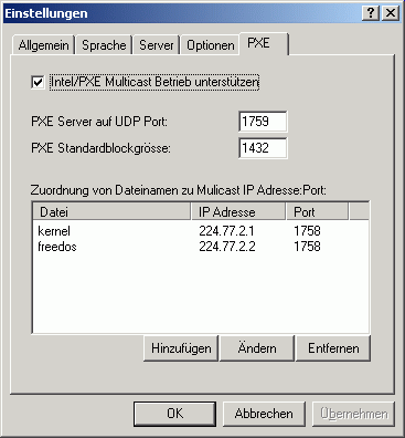
The Intel/PXE specification uses a different protocol for multicast operation. Multicast configuration parameters are sent to clients using DHCP options.- Multicast requests are directed from a client to an extra server port.
- The default blocksize is 1432 bytes.
- Each file downloaded using multicast operation is send to an unique multicast IP address and port.
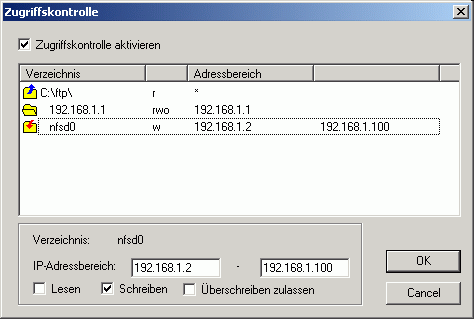
- Access control
-
Iec 949 Pdf Work |work| Link
The standard follows a three-step process to determine the maximum safe current a conductor can handle during a short circuit: Calculate Adiabatic Short-Circuit Current ( IADcap I sub cap A cap D end-sub
): This assumes all heat remains within the conductor and none is dissipated to the surrounding environment.
Calculate a Modifying Factor: This factor accounts for non-adiabatic heating, which is the heat dissipation that occurs in real-world scenarios.
Multiply for the Permissible Current: The final permissible current is the product of the adiabatic current and the modifying factor. Primary Calculation Formula (Adiabatic)
For durations up to 5 seconds, the standard uses the following equation to find the adiabatic current ( IADcap I sub cap A cap D end-sub
IAD=K×St×ln(θf+βθi+β)cap I sub cap A cap D end-sub equals the fraction with numerator cap K cross cap S and denominator the square root of t end-root end-fraction cross the square root of l n open paren the fraction with numerator theta sub f plus beta and denominator theta sub i plus beta end-fraction close paren end-root IADcap I sub cap A cap D end-sub : Permissible adiabatic short-circuit current (A). : Cross-sectional area of the conductor ( mm2m m squared : Duration of the short circuit (s). θitheta sub i θftheta sub f : Initial and final temperatures (°C). : Material-specific constants. Accessing the Full Document
The standard is a copyrighted publication and is typically available for purchase in PDF format from official standards organizations:
IEC 60949 (formerly IEC 949) provides methodologies for calculating thermally permissible short-circuit currents in cables, covering both adiabatic and non-adiabatic heating effects. The standard is used to determine safe cable sizing and metallic screen requirements by analyzing fault currents, particularly for durations between 0.35 and 1.0 seconds. Access the official standard via the ANSI Webstore ANSI Webstore DS/IEC 949:1990 - ANSI Webstore
In the sterile, blue-tinted light of the Grid-Sync laboratory, Elias stared at a corrupted file icon on his tablet. The title read: IEC 949: Calculation of thermally permissible short-circuit currents. iec 949 pdf work
It was 3:00 AM. In three hours, the municipal substation would go live. If his calculations for the non-adiabatic heating of the cable screens were off by even a fraction, the surge wouldn't just trip a breaker—it would melt the underground infrastructure of half the city.
"Why won't you open?" Elias muttered, his thumb hovering over the 'Retry' button.
The PDF was a beast of a document. Unlike its simpler cousin, IEC 60909, which handled the "how much" of a short circuit, IEC 949 was about the "how long." It accounted for the heat that escaped into the insulation—the "non-adiabatic" effect that made the difference between a cable surviving a fault or turning into a fuse.
He needed the specific factors for copper screening. He had the initial temperature ( 20∘C20 raised to the composed with power cap C ) and the final permissible limit ( 160∘C160 raised to the composed with power cap C ), but without the
factors buried in the PDF’s tables, he was guessing. And in high-voltage engineering, a guess is just a slow-motion disaster.
Suddenly, the screen flickered. The progress bar jumped from 0% to 100%. The document bloomed across his screen, dense with Greek symbols and logarithmic equations.
Elias scanned the pages, his eyes darting until he found Table 1. He cross-referenced the cross-sectional area of the screens with the projected fault duration of 1.2 seconds. He plugged the values into his software.
The simulation curve shifted. The red line—the thermal limit—stayed safely above the blue line of the power surge. The standard follows a three-step process to determine
"Work," Elias whispered, watching the simulation reach steady-state.
He hit 'Confirm.' Outside, the first hint of dawn touched the horizon. The city would wake up, flip their switches, and never know that a single PDF and a tired engineer had kept their world from burning.
The IEC 60949 standard (often referred to in technical circles as IEC 949) is a foundational document in electrical engineering that establishes the methodology for calculating thermally permissible short-circuit currents. This standard is vital for the safe design of power systems, as it ensures that cables and their components can withstand the extreme heat generated during a fault without suffering irreversible damage to their insulation or structural integrity. Core Purpose of the IEC 60949 Standard
The primary goal of IEC 60949 is to provide a uniform method for determining the maximum current a cable's current-carrying components (such as conductors, sheaths, and screens) can handle for a specific duration.
Unlike simpler models that assume all heat is retained within the conductor (the adiabatic approach), IEC 60949 introduces factors that account for non-adiabatic heating effects—the heat that dissipates into surrounding materials like insulation or cable bedding during the short circuit. The Two-Stage Calculation Methodology
The standard follows a structured approach to arrive at the final permissible current: Adiabatic Short-Circuit Current ( IADcap I sub cap A cap D end-sub
): This is the baseline calculation assuming no heat escapes the conductor. The formula typically used for this is:
IAD=K⋅St⋅ln(θf+βθi+β)cap I sub cap A cap D end-sub equals the fraction with numerator cap K center dot cap S and denominator the square root of t end-root end-fraction center dot the square root of l n open paren the fraction with numerator theta sub f plus beta and denominator theta sub i plus beta end-fraction close paren end-root : Cross-sectional area of the conductor ( mm2m m squared : Duration of the short circuit (seconds). θitheta sub i θftheta sub f : Initial and final permissible temperatures ( ∘Craised to the composed with power cap C : Material-specific constants (e.g., for copper, Mistake 4: Mixing units The standard uses mm²
Non-Adiabatic Modifying Factor: The standard then applies a modifying factor to the adiabatic result to account for heat transfer to adjacent materials. This allows for a more realistic (and often higher) permissible current rating, which can lead to cost savings by preventing over-sizing of cables. Common Applications in Power Systems IEC 60949 Compliance for High Voltage Cable Systems
Mistake 4: Mixing units
The standard uses mm² for area and seconds for time. Using cm² or milliseconds will produce dangerously wrong results.
Part 6: Tools to Simplify IEC 949 PDF Work
Doing these calculations manually is tedious. Most engineers use:
1. Compliance with International Standards
Utility companies and regulatory bodies require proof that cables can handle fault conditions. A simple adiabatic calculation is often too strict. Using IEC 60949 provides a technically justifiable, non-conservative rating.
4.1 Protective Device Coordination
The primary application of IEC 949 is to ensure coordination between the cable thermal capacity and the protective device (circuit breaker or fuse) characteristics. Engineers must verify that the "let-through energy" ($I^2t$) of the protective device is less than the "withstand energy" of the cable.
$$ (I^2t)device < (I^2t)cable $$
If this condition is not met, the cable may suffer thermal damage or ignite before the breaker trips.
2.1 The Adiabatic Assumption
For very short fault durations (typically less than 5 seconds), the standard often employs an adiabatic approximation. This assumes that all heat generated in the conductor remains within the conductor during the fault because there is insufficient time for heat to transfer to the insulation or surroundings.
- Help
- Contents
- starts a HTML browser displaying the manual.
- Register
- prompts for the license key and your name, company. Check the Info menu to find out if the license information was accepted.
- Show License
- displays the conditions for using this software.
- About...
- displays program version information.
Using the TFTP Client
TFTP.EXE is a Win32 command line TFTP client.The implementation of the client as a command line program allows easy use of the client for automated tftp data transfer from application or procedures.
Usage: tftp [Options] server GET|PUT file [local]
- server: IP address or name of the TFTP server
- file: Name of file to transfer
- local: Local name of file
- Options:
- -a mode ASCII, default OCTET
- -b<blocksize> block size in bytes, default 512
- -d write debug messages
- -l show transfer activity
- -o override if local file exists
- -p pipe: send data from stdin/receive data to stdout
- -r<retries> number of retries on timeout
- -s disable transfer size option, default enabled
- -t<timeout> retransmission timeout in seconds, default 1s